![]()
![]()
![]()
![]()
![]()
![]()
![]()
![]()
![]()
![]()
![]()
![]()
![]()
![]()
![]()
| Technology | ||
| Power Factor Correction PFC | ||
|
|
||
General
Description:
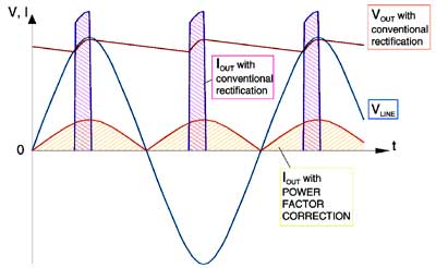
Harmonics must be filtered; Rectifiers have to be over-designed and need cooling. This just shows a few problems power generating plants are confronted with. They charge for all the investment and costs incurred by operating such systems on their lines; not to speak about environmental problems. Current on an ohmic load flows during the full time of a half cycle, starting from zero to peak and back to zero. This current is sinusoidal and in phase with the Source Voltage. A much smaller average current flows compared with the pulsed peak currents of conventional rectifiers. Power Factor Correction simulates this ideal "Ohmic Load" condition through an electronically controlled active rectification process. In order to comply with these requirements Schock offers active Power Factor control on most of its products.
|
||
|
|
||
Features: Schock Power Corporation offers Power Factor Correction in many of its power supplies and battery chargers. The simulation of an ohmic load, results in a sinusoidal current, which is drawn from line. This method achieves a Power Factor of close to ONE. Universal Input Voltage Range from 90 to 270VAC (50/60Hz) can be accommodated - without range switching Much Higher Power (1.65kW) can be drawn from a 15A wall plug. With regular rectification only about 0.8kW are available, causing all mentioned disadvantages Conduction Angle is almost 180O, respectively 360O Power Factor > 0.9 (usually 0.97 to 0.99) Overall Lower Power Installation Costs No Phase Shifts are caused No or Low RF, due to: a.) lower peak current levels b.) the basic arrangement of circuit elements c.) shift of RF spectrum to much higher frequencies, and therefore easier to filter Common RF Filter for paralleled supplies are possible. Lower Risk and Costs for agency approval Competitive Advantages Advanced state of the art Products Smaller physical size of parts High Efficiency.
|
||